Application
The ERK B50 3P+1 fulfills the requirements of Class B as defined by DIN VDE 0675 Part 65 and Class I as defined by IEC 61643-1; it is designed for use at lightning protection zone 0 - >1 in accordance with the zone concept set out in IEC 61312-1. Where there is a lightning protection installation in the building, the protector establishes the lightning equipotential bonding with the power supply lines.
Installation Location
The Class B surge protection devices in the main power supply system are selected and set on according to the type of mains system and must comply with DIN VDE 0100, Part 534 and IEC 60364.
Electrical Connection
The connection is made between the connection lines (L1, L2, L3) and the neutral conductor (N) or the earth of the loads. The conductors can be connected in two ways on each connection side for Lx and N/PE conductors. Protected and unprotected lines must not be laid immediately parallel next to each other. They must be separated or shield from each other in such a way that there is no possibility of overvoltage crossover from unprotected lines to protected lines.
Connection to the outer conductors / neutral conductors
When connecting the active conductors L1, L2, L3 and neutral line, remember they carry considerable lightning currents. They should therefore be designed with a min. cross-section of 16mm2.
Connection to the Earth
The earth line of the arrester(s) is connected to a copper line of min. cross-section 16mm2 (VDE 0185, Part 103) or IEC 61024-1 by the shortest route. Parallel routing with protected electrical lines must be avoided. The earthed equipotential bonding rail can be used as a connection point with equipotential bonding in accordance with VDE 0100, Part 540. If the arresters are installed directly in the distribution system, the earth conductor should preferably be connected to the potential busbars there. Ensure that the connection between the potential busebars and the main equipotential rail consist of min. 16mm2 Cu. When installing several EK B50 and the EK B NPE next to each other, a common neutral conductor connection can also be made via a separate 16mm2 connection in the side channel of the arrester.
Installation site and electrical connection
The ERK C25 3P+1 are overvoltage arrester of service requipment category C under VDE 0675, Part 6 according to overvoltage protection category III under VDE 0100, Part 1 and the arrestor are installed as close as possible in front of the protected system ( supply entry ). The overvoltage protection module specially developed for use in TT and IT networks, has a common N connection. The 3 modules are installed between L and N. The N-PE protector is connected to the ground lead.
Connection to the outer and neutral connector
The For the connection lines to overvoltage arrestor you normally choose the same cross section as for the outer and neutral conductors.
Connection to grounding
The ground line of the arrester is connected as short as possible to the grounding of the load system ( VDE 0185, Part 1 ). Parallel exposure with other electric lines should be avoided. The appropriate connecting point in electric load systems with equipotential bonding under VDE 0190 is the grounded equipotential busbar. Notes The Always make sure that the grounding of the N-PE protector is connected to the grounding of the load system. Because of the combined design of arrestor and N-PE protector, it is good practice to install the overvoltage protection module in front of the fault current circuit breaker.
Application
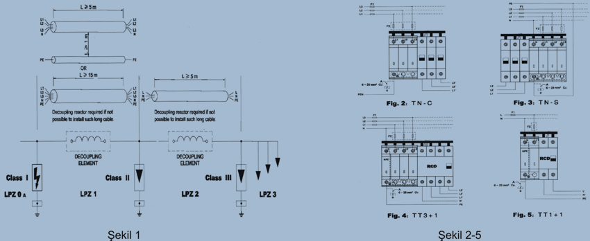
The arresters are designed for limiting surge in low-voltage installations. They also protect subsequently arranged installations and equipment ( e.g. EDP-system, telecommunications system, etc. ) against surge caused by switching operations, electrostatic discharges, distant lightning or direct lightning. Generally, in accordance with lightning protection equipotential bonding, lightning current arresters of class I used for protecting the low-voltage installation against the effects of direct lightning and surge, should be installed in the main power supply system, such as the service entrance, the upstream of meter or the downstream main distribution board, forming the boundary from lightning protection zone 0A to LPZ1 within the Lightning Protection Zones Concept; A typical application for overvoltage arresters of Class II against the effect of surge caused by atmospheric discharge or switching transients, is the main or sub-distribution board of low-voltage installations forming the boundary from LPZ1 to LPZ2;And the application of the surge arresters of Class III is for protection of sensitive equipments against surge, installed on LPZ2 to LPZ3. See Figure 1.
When several arresters are installed in one circuit, they must be coordinated with respect to their energy capabilities to ensure that the equipment to be protected with the lowest voltage protection level is not overloaded. For this purpose, dimensioned decoupling impedances are requires between these arresters of different classes. It can also achieved by the impedance of the cable connecting them. Energy coordination of arresters of Class I and II requires an inductance 15uH. The inductance of a cable also depends on the mounting of the protective conductor PE. When PE is included in the cable, the min. cable length between arresters of Class I and II must be at least 15m irrespective of the laying ( straight or in loops ); when PE is mounted separately and the isolating distance is at least 1 m from L1, L2, L3 and N, the min. cable length is 5 m. And 5 m long cables are sufficient for decoupling of arresters of Class II and III. However, if it’s impossible to install such long cables, the use of decoupling element is necessary to coordinate these arresters. For detail see Figure 1. Because the arresters installed between phase conductor and protective one or neutral and protective conductor can cause a short circuit between line and protective conductor of the installation in case of an overload, the measures for protection of persons against electric shock are especially important. Therefore, it must be disconnected from the installation within a time specified to ensure protection against indirect contact. Apart from that, the arresters should be installed on the power side of the R.C.D. due to their impulse current withstand capability.
Figure 2 to 5 show the suggested circuit diagrams for the installation of arresters, A equipotential bonding cable in the figure depends on the cross-sectional area of the protective conductor coming from the service entry point or main distribution board, it is 0.5X the cross sectional area of the main conductor, subject to a minimum of 10mm2 Cu and a maximum of 25mm2 Cu ( VDE 0100, Part 540, Table 9). The connecting line conductor must ensure that the conductor insulation is stripped back to a length of 10mm; this makes it safe from finger touch. The input of the arresters is connected to line conductors ( L1, L2, L3 ) or neutral conductor ( N ), and the output is earthed ( via PE or PEN ), whereas a connection to the equipotential bonding must be provide. The earthing conductor is to be connected to earth via the shortest possible path, such as equipotential bonding / equipotential bar, earth electrode.
Safety Instruction
The arresters are only to be installed by an electrically skilled person in accordance with correlative regulations. Its use is only permitted due to the conditions mentioned and shown in the installation instructions. The function of the arresters can be interfered when it is used in applications exceeding the values stated in the Technical Data. Furthermore, the arresters are to be checked by the electrically skilled person for signs of external damage prior to installation. If any damage or other defect is detected in this check, the arrester must not be installed. However, opening or otherwise tampering with the arresters is not permitted for safety reasons. Tampering with the equipment invalidate the warranty.
Fault Indicator / Maintenance Safety Instruction
The energy load of the arresters is supervised by an integrated thermodynamic control device. In case of a fault (thermal overload) this supervisory device automatically disconnects the arrester from the power supply; electrical equipment installed downstream is then no longer protected against surges. The fault is indicated by red defect indicator in the window of module. If the indicate becomes red, the module with red indicator must be replace immediately, which is fault. Also see figure 6. It must be paid attention to that the measurement result of insulation of the electrical installation can be affected because of the earth connections of the arrester. Therefore, it is necessary to remove the protection module from the base for insulation measurement.
| ERK C25 3P+1 | TNC
TNS | TT | | L-N | N-PE | | Nominal voltage Un | 230V / 50Hz | | Max. continuous operating voltage Uc | 385V / 50Hz | 255V / 50Hz | | Nominal discharge current (8/20us) Isn | 10kA | 30kA | | Max. discharge current (8/20us) Imax | 25kA | 65kA | | Voltage protection level Up | < 1kV | < 1.2kV | | Response time Ta | 25ns | 100ns | | Max backup fuse | 125AgL/gG | -- | | Short-circuit withstand capability with max backup fuse | 25kA / 50Hz | -- | | Operating temperature | -40℃ ~ +80℃ | | Degree of protection | IP20 | |